Using markerless motion capture to explore changes in tackle kinematics and load based tackling technique proficiency
Authors
University of Cape Town (UCT): African Robotic Unit (ARU) and Sport Science and Medicine.
Lara Paul: lara.paul.0995@gmail.com
Sharief Hendricks: sharief.hendricks01@gmail.com
Amir Patel: Amir.patel@ucl.ac.uk
Zubair Martin: zubairmartin.martin@gmail.com
NOTE: training and test video data can be requested using the above email addresses.
Model Name
rugby-tackle-dlc
Model Description
This DeepLabCut-based model performs markerless pose estimation on rugby tackling scenarios recorded from multiple synchronized cameras. The goal is to automate kinematic analysis such as velocity, acceleration, and impact force during controlled tackles. The model supports full 3D reconstruction and biomechanical analysis of both the athlete and the tackle bag.
Model Architecture
- Framework: DeepLabCut (TensorFlow backend)
- Backbone: ResNet-101
- Training Frames: 1162 manually labeled frames
- Keypoints Tracked:
- Rugby player: ankles, knees, hips, shoulders, wrists, elbows, chin, forehead
- Punching bag: top, upper quartile, middle, lower quartile, bottom
- Training/Testing Split: 95% train / 5% test
- Likelihood Threshold: 0.5
Training Dataset
- Source: Controlled rugby tackle drills at UCT Mechatronics Lab
- Capture Setup: 3 synchronized GoPro cameras (1920×1080), checkerboard calibration
- Annotations: Manual tagging of player and bag points at key frames
- Calibration: OpenCV intrinsics + pairwise extrinsics with sparse bundle adjustment
Evaluation Metrics
- RMSE: Computed between manual and model-predicted keypoints
- Reprojection Error: Used during camera calibration to ensure 3D reconstruction fidelity
Folder Structure
- Calibration: Has all calibration data (used in experiments)
- Model Setup: Has configuration files for dlc setup
- dlc models: Has the latest trained models.
- python-3d-toolbox: has all relavent code to run evaluation.
python-video-utils: has code to edit video files (created by Liam Clark).
Methodology for Training Data
The dlc models adopts the TensorFlow engine, with training iterations highlighting model data from trained and tested using a YAML file [1]. Training data set (which trains the network) and a test data set(to evaluate the network) in order to produce a model. Random frames were selected and labelled (indicating the position of certain body parts).
The first step of developing the model was the selection of labelled data. The labelled data was obtained by selecting frames of existing tackle footage (rugby player tackling a moving/appraoching punching bag), therafter taging varuous points:
- for the rugby subject:ankles, knees, hip sides, wrists, elbows, shoulders, chin, and forehead
- for the punching bag: top, upper quartile, middle, lower quartile, and bottom.
Around 1,162 frames were labelled for the training data set. These frames were selected to capture the complete breadth of the tackle behavior for numerous rugby players to capture the diversity of the behavior with respect to postures. Specifically, the selected frames focused on extracting frames from a period of the video that contains interesting behaviors which include the rugby player to punching bag contact, and rugbyplayer-puniching bag to ground contact.
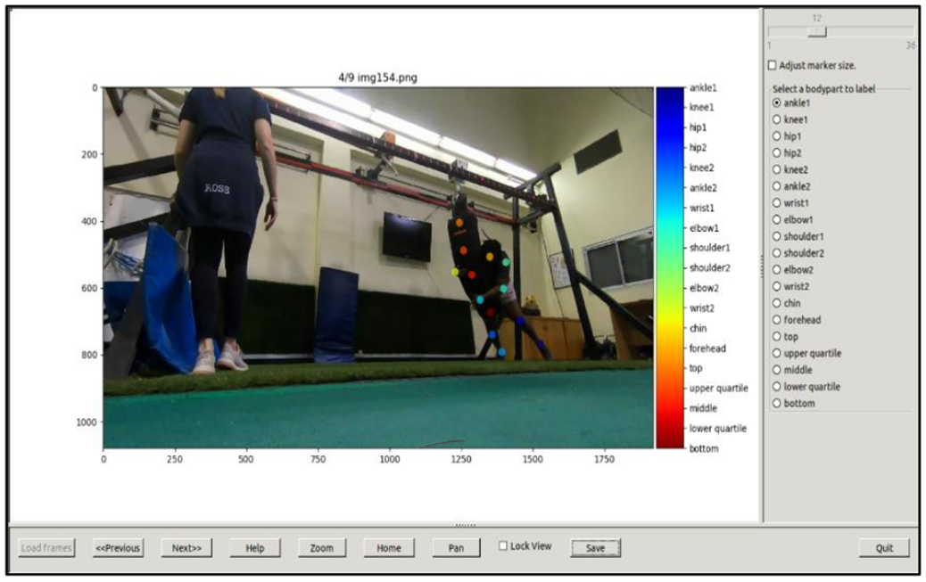 Figure 1: Labelled data (tagging image)
The labelled images were used to train and test the model. The training data was used to train the network, while the test data set was used for evaluating the network. Given the availability of sufficient computational resources, training time, and the requirement for complex features, the Resnet 101 neural network model was used. Futherore, the training fraction (test to train data) was set to 95% training and 5% testing with default/no augementation settings. The reason for this is that there were many images available and due to the model complexity.
To evaluate the model, the average root mean square error (RMSE) was calculated between the manual labels and the ones predicted by DeepLabCut, with the likelihood of confident predictions set to 0.5. This was done by placing a random video and viewing whether the network would label the points correctly.
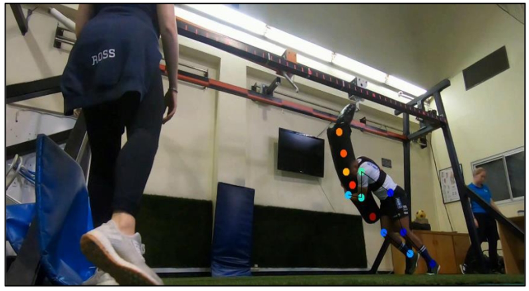 Figure 2: Deeplabcut pose estimation result.
How to Use - Setup Camera Calibration
In order to adopt real world video data into analysing the data using Deeplabcut, calibration methods were crucial. Camera calibration involves the estimation of the camera parameters with the goal of rectifying lens distortion, identification of the camera location, and determine the size of an object in world units. The camera parameters include intrinsics, extrinsics, and distortion coefficients [2]. To determine these, both 3D world points and their corresponding 2D image points were required. This study adopted a calibration approach developed by L.Clark, which uses OpenCV and drew inspiration from DeepLabCut’s website on camera calibration techniques [3] , [4].
In order to calibrate the cameras per set/session, videos of the experimenter were recorded moving a calibration checkerboard in front of the cameras using three GoPros positioned equally along the experimental platform. Intrinsic calibration parameters consist of the focal length pixels, optical center pixels, and skew coefficient. To obtain this, a calibration checkerboard was used. To determine this, using the camera resolution of the cameras (1920 × 1080), camera model (standard), and the calibration board parameters.
The extrinsic parameters involve rotation and translation between cameras, with the coordinate system’s origin being at the optical center with the x and y being the image plane. In order to calibrate the extrinsic parameters , each consecutive pair of cameras (i.e. 1-2 and 2-3) was setup such that the calibration board was viewed at the same time for several frames. For the calibration algorithm, 30 frames were selected from each camera across the entire platform. An algirthm was generated to find the frames in the videos which contain the calibration board, locating the corner points. This was done by specifying the calibration board shape and the length of the square edges: 8x6 and a square edge length of 40mm. To determine the extrinsic calibration parameters, the camera properties (resolution and model), calibration board parameters, along with an initial pairwise RMS reprojection error approach was adopted to track data capture validility. Thereafter, the focus was on creating initial 3D estimates for optimisation with estimating pairwise points between cameras. This allowed the performance of sparse bundle adjustment.
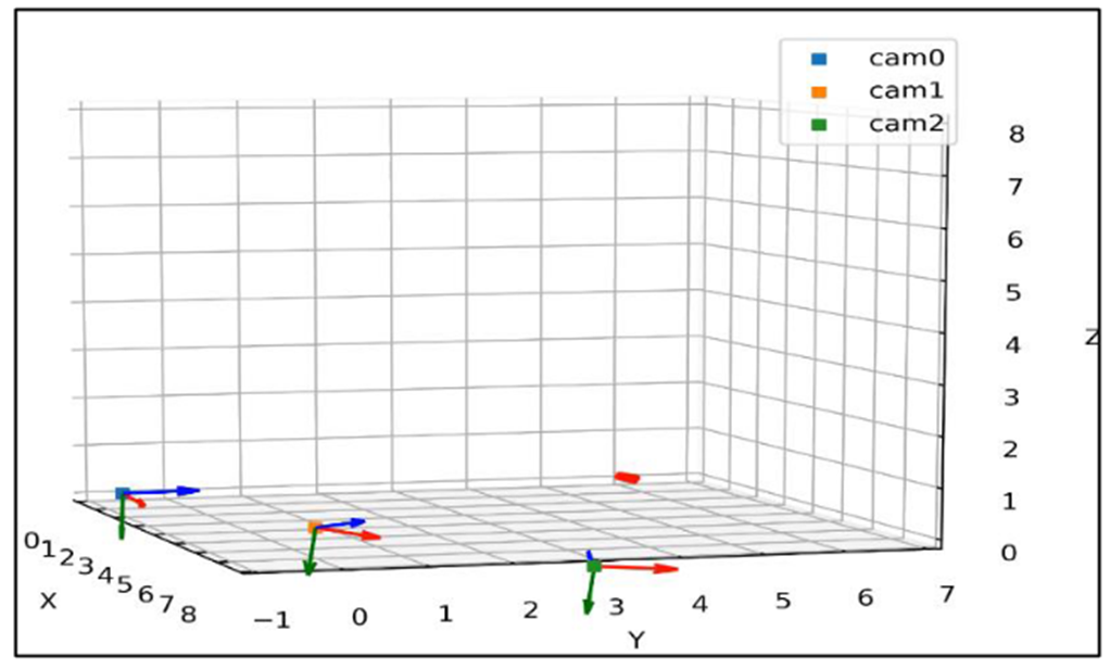 Figure 3: Camera calibration result.
How to Use - Tackle Evaluation
This section will describe the steps on how to evaulate the data (using the provided code):
- Open the file: combine134.py, and fill in the following information:
directory = '/home/...' # Directory of folder to place evaluated data files
folder = '/home/...'# Directory of folder with all the data (videos of tackle to evaluate)
project_dir = '/home/...' # Directory of camera calibration data
actual_to_truncate_frame = [x,x] # Actual frames at which the tackle starts and ends (bag touch ground), respectively
mass = x # mass of tackler
temp = 'Tackle6_session12_set2' # Name of tackle number, session, and set
spreadsheetname = 'spreadsheet_'+temp #spreadsheet name to store all the evalated data
GP_used = GoPro pairs that were used [134], [13], [14], or [34]
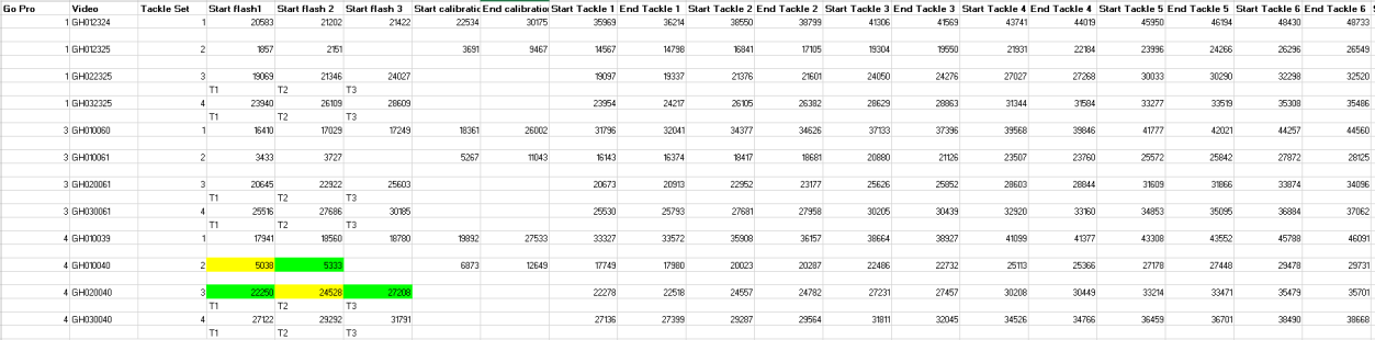 Figure 4: Example layout of spreadsheet (input data).
Thereafter, run the combine134.py, this will do the following:
Step 1: Median_Filter_outliers.py (removes all outlier data - outside the bounds of a 500x500 box form pose estimation)
Step 2: reconstruction.py (3D triangulation reconstruction of the data using Liam Clark's cameratoolbox - linked above, using camera calibration data)
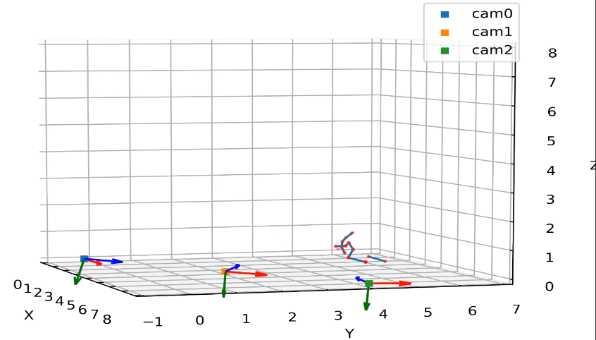
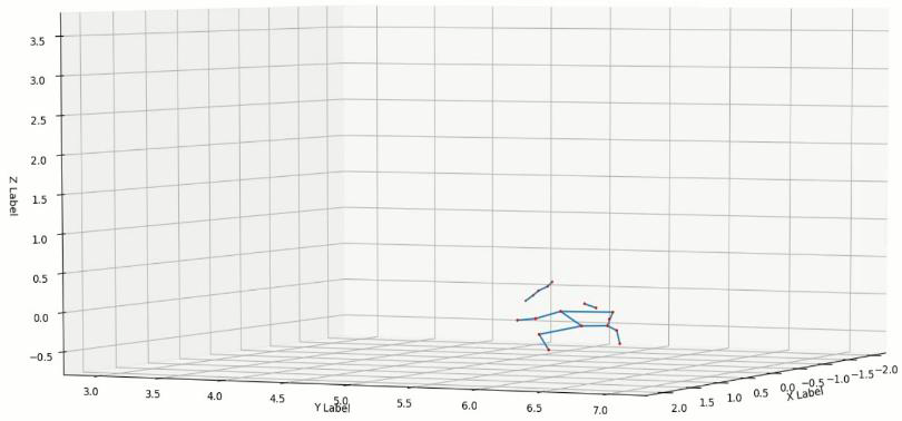 Figure 6: Resulting 3D constructed pose estimation (example).
Step 3: Select_Data.py (select and seperate data into a usable format, and points with likelihood threshold > 0.9)
Step 4: filter_data_average.py (applies median filter to data, to reduce noise/jitter)
Step 5: velocity.py (finds velocity and acceleration of evaluated positions/joints)
Step 6: worldtocam_frame.py (Rotate points from world frame to middle camera frame (GP3))
Step 7: cubic_spline_new_file_interpolated.py (Generate spline through data points, for smoothing of data)
Step 8: EndandStart.py (Estimates where the start end frame of tackle compared to the actual)
Step 9: SpreadSheet.py (Calculates: kinetic energy, impact force, power, momentum, relative position, updated acceleration, updated velocity, and distance travelled)
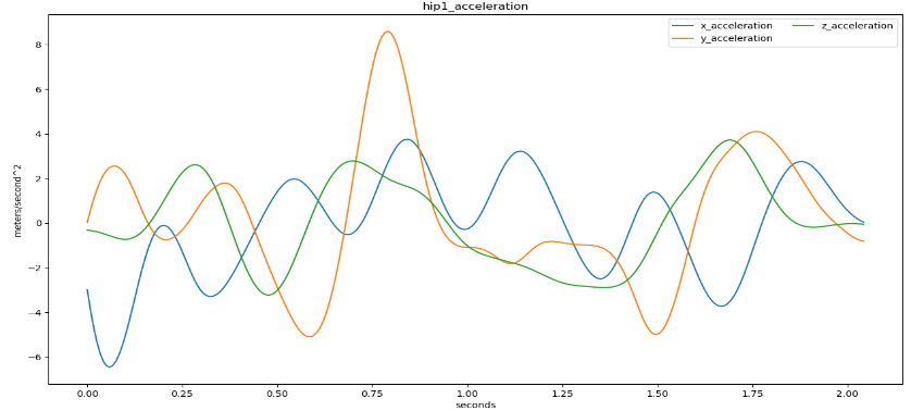
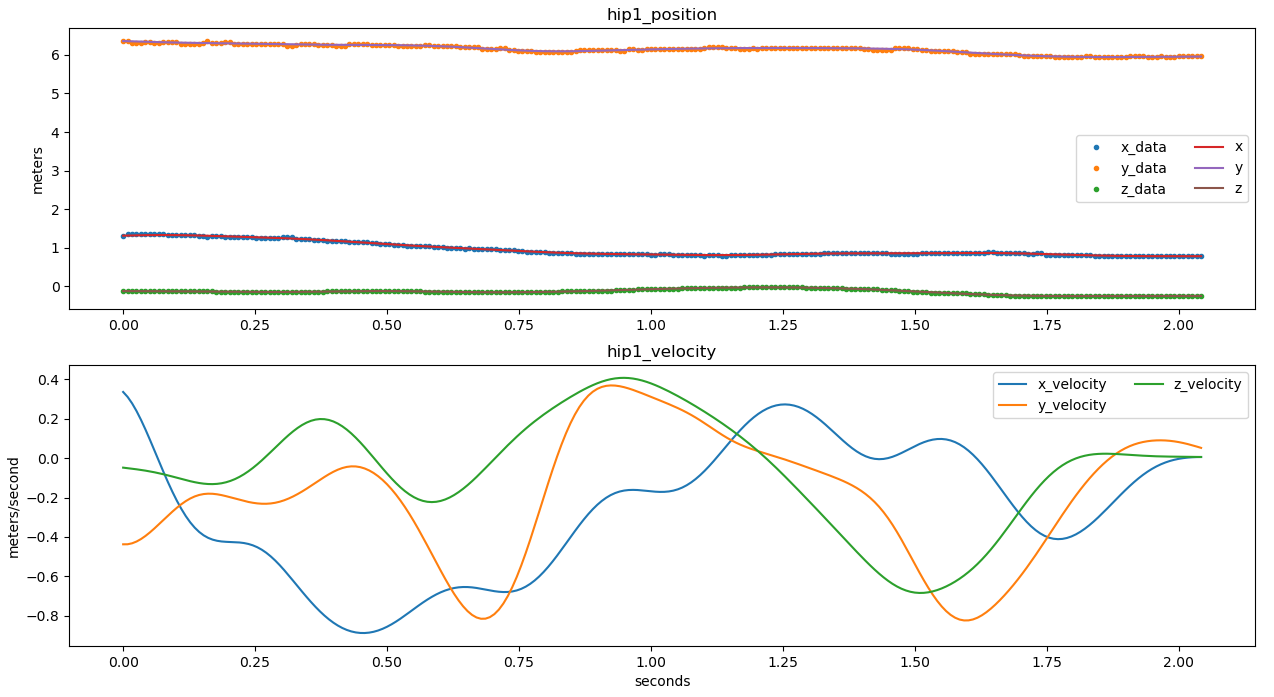
Figure 6: Resulting filtered and smoothed kinematic data.
These scripts must be executable as modules with a main() entry point, as used in combine134.py file.
[1] https://github.com/DeepLabCut/DeepLabCut/blob/main/docs/standardDeepLabCut_UserGuide.md
[2] https://www.mathworks.com/help/vision/ug/camera-calibration.html
[3] https://github.com/liamclarkza/python_3d_toolbox
[4] https://github.com/DeepLabCut/DeepLabCut/blob/main/docs/Overviewof3D.md